Gabions Products
- Military Gabions

- Hot Dipped Galvanized Gabion Mesh Cells
- Welded Mesh Gabions Architectural Wall Cladding
- Gabions (Gabiony)
- Galfan + PVC Coated Gabions
- Gabion Mattresses for Flood Protection Embankment
- Planted Gabion Walls
- Gabions and Geotextiles for Bridge Construction
- Gabion Basket Hot Dip Galvanized
- Gabions P. V. C. Coated Galvanised Wire Box
- Gabions River Training Works
- Geotextile Fabric
- Woven Wire Mesh Cages for Gabion Project
- Gabion Fence
- Welded Gabions Coating Galfan
- Gabion Baskets Double Twisted Galvanized
- Triple Twisted Wire Mesh Gabions
- Gabion Box
- Woven Gabions
- Gabion Baskets
- Wire Mesh Gabion Mattress
- Gabion Cages (Stone Box)
- Gabion Wall
- Hexagonal Gabions Netting
- Gabions Machine
- Welded Gabions
- Sack Gabions
- Reinforced Gabions
- Gabion faced reinforced soil walls
- Gabion Mattress
- Gabions for Water Conservancy
- Gabions for Bridge Protection System
- Gabion Wall Drop Structures
- Modular Gabions as Architectural Elements
- Gravity Wall of Gabions
- Gabions for Headwalls or Wingwalls
- Channel Linings
- Modular Gabions for Rockfall Netting System
Soil Reinforcing Gabion Walls - Gabion Faced Soil Retaining Wall
Gabion faced reinforced soil walls are a system whose structural stability is achieved by virtue of reinforcement layers of polymer geogrids and steel mesh gabion baskets. These polymer geogrids and steel mesh gabion basket are placed in the soil to form a soil retaining work.
This type of structure costs less time and labor.
As with mass of gravity walls, the gabion face is inclined at 6 degrees to the vertical and/or stepped.
Designers can select geogrids from a wide range of soil reinforcement systems to suit specific soil conditions including:
• Gabion faced soil reinforcement system using steel geogrids;
• Vegetating face slope reinforcement system using steel geogrids;
• Heavy-duty sheathed geogrids with strengths up to 1250kN/m for basal reinforcement and piled embankments;
• Polymer geogrids for slope reinforcement, segmental retaining walls and blockwork walls.
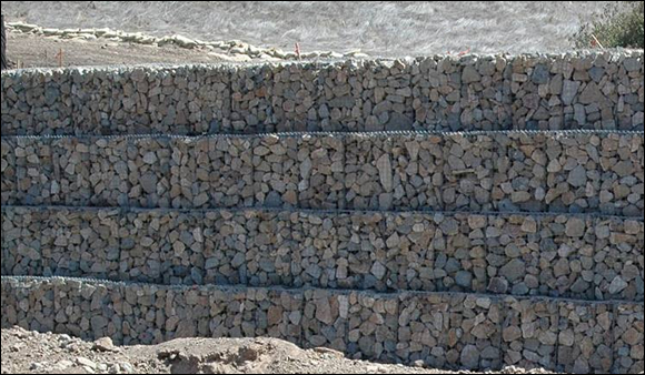
Gabion walls with a stepped front face
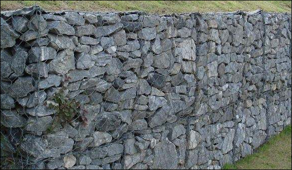
Gabion Cages for Retaining Walls, Galvanised Steel Gabion Baskets
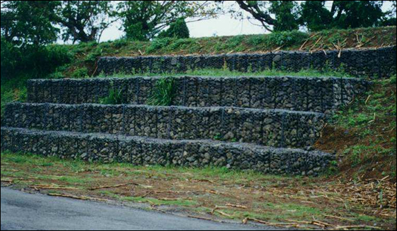
Gabion Faced Reinforced Soil Walls
Concrete Surround to Pipes (Encasement)
Reinforced Concrete Encasement shall be installed as indicated on the Drawings. Concrete and reinforcing steel shall be as specified in the Concrete Reinforcement, and Cast-in-Place Concrete Sections. All pipes to be encased shall be suitably supported and blocked in proper position and shall be anchored against flotation.
Pipes shall be supported and jointed at the correct level clear of the trench bottom, each one supported on two blocks of pre-cast concrete of suitable height, one at each end of the pipe. Concrete shall then be poured and rammed beneath and around the pipes in one operation and finished off to the level and dimensions shown on the Drawings. In order to ensure that the space underneath the pipe is well filled with concrete, it shall be first poured on the side of the pipe until it rises and appears on the other side. Thereafter, concrete shall be poured on both sides of the pipes to the required height.
The pre-cast blocks shall first be properly set on the trench bottom and boned to the correct position and level. The pipes shall then be laid on the blocks and properly centred, jointed and finally brought to the correct gradient by the application of wooden wedges one on each side of the pipe and between the pipe and the concrete blocks. These wedges shall remain left-in whilst the pipes are jointed and tested, as herein specified and during the pouring of the concrete beneath and around the pipes. Where the concrete while being poured would otherwise cause the pipes to float, pipes shall be effectively anchored to prevent such flotation.
Concrete Carpet
A plain concrete carpet (layer) shall be laid below the surface reinstatement of asphalt roads as shown on the Drawings. The concrete carpet shall be provided at road crossings. In accordance with the requirements of local authorities or as directed by the Engineer, a plain concrete carpet shall also be placed at other locations where pipelines are constructed under asphalt roads, including where pipelines are laid longitudinally in asphalt roads. For certain road crossings and in case of local authority requirements, pipelines shall cross roads in trench-less excavation.